ASME B16.47 Series A Flanges Class 900 Dimensions and Technical Drawings

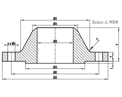
ASME B16.47 Series A 900# Welding Neck Flange with RF

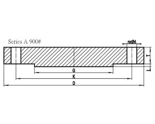
ASME B16.47 Series A Class 900 Blind Flange with RF
DOWNLOAD ASME B16.47 SERIES A FLANGES CLASS 900 DIMENSIONS AND TECHNICAL DRAWINGS PDF
Get Complete details of ANSI/ASME B16.47 Standard Flange
900# B16.47 Series A Flanges Dimensions
B16.47 Dimensions in MM
| NPS |
D |
K |
G |
X |
| 26″ |
1085 |
952.5 |
749 |
775 |
| 28″ |
1170 |
1022.4 |
800 |
832 |
| 30″ |
1230 |
1085.8 |
857 |
889 |
| 32″ |
1315 |
1155.7 |
914 |
946 |
| 34″ |
1395 |
1225.6 |
965 |
1006 |
| 36″ |
1460 |
1289.0 |
1022 |
1064 |
| 38″ |
1460 |
1289.0 |
1099 |
1073 |
| 40″ |
1510 |
1339.8 |
1162 |
1127 |
| 42″ |
1560 |
1390.6 |
1213 |
1176 |
| 44″ |
1650 |
1463.7 |
1270 |
1235 |
| 46″ |
1735 |
1536.7 |
1334 |
1292 |
| 48″ |
1785 |
1587.5 |
1384 |
1343 |
| 50″ |
– |
– |
– |
– |
| 52″ |
– |
– |
– |
– |
| 54″ |
– |
– |
– |
– |
| 56″ |
– |
– |
– |
– |
| 58″ |
– |
– |
– |
– |
| 60″ |
– |
– |
– |
– |
General Note:
- All dimensions are in MM.
- D: outside diameter of flange.
- K: diameter of bolt circle.
- G: diameter of raised face.
- X: diameter of hub of flange.
| NPS |
A |
TBL |
TWN |
Y |
| 26″ |
660.4 |
160.4 |
139.7 |
286 |
| 28″ |
711.2 |
171.5 |
142.9 |
298 |
| 30″ |
762.0 |
182.6 |
149.3 |
311 |
| 32″ |
812.8 |
193.7 |
158.8 |
330 |
| 34″ |
863.6 |
204.8 |
165.1 |
349 |
| 36″ |
914.4 |
214.4 |
171.5 |
362 |
| 38″ |
965.2 |
215.9 |
190.5 |
352 |
| 40″ |
1016.0 |
223.9 |
196.9 |
364 |
| 42″ |
1066.8 |
231.8 |
206.4 |
371 |
| 44″ |
1117.6 |
242.9 |
214.4 |
391 |
| 46″ |
1168.4 |
255.6 |
225.5 |
411 |
| 48″ |
1219.2 |
263.6 |
233.4 |
419 |
| 50″ |
– |
– |
– |
– |
| 52″ |
– |
– |
– |
– |
| 54″ |
– |
– |
– |
– |
| 56″ |
– |
– |
– |
– |
| 58″ |
– |
– |
– |
– |
| 60″ |
– |
– |
– |
– |
General Note:
- All dimensions are in MM.
- A: Diameter of hub top of WN.
- TBL: minimum thickness of blind flange.
- TWN: minimum thickness of WN flange.
- Y: length through hub of WN.
- t: 7mm height of RF for Class 900 Series A flange.
| NPS |
n |
d |
l |
r |
| 26″ |
20 |
2-7/8 |
2-3/4 |
11 |
| 28″ |
20 |
3-1/8 |
3 |
13 |
| 30″ |
20 |
3-1/8 |
3 |
13 |
| 32″ |
20 |
3-3/8 |
3-1/4 |
13 |
| 34″ |
20 |
3-5/8 |
3-1/2 |
14 |
| 36″ |
20 |
3-5/8 |
3-1/2 |
14 |
| 38″ |
20 |
3-5/8 |
3-1/2 |
19 |
| 40″ |
24 |
3-5/8 |
3-1/2 |
21 |
| 42″ |
24 |
3-5/8 |
3-1/2 |
21 |
| 44″ |
24 |
3-7/8 |
3-3/4 |
22 |
| 46″ |
24 |
4-1/8 |
4 |
22 |
| 48″ |
24 |
4-1/8 |
4 |
24 |
| 50″ |
– |
– |
– |
– |
| 52″ |
– |
– |
– |
– |
| 54″ |
– |
– |
– |
– |
| 56″ |
– |
– |
– |
– |
| 58″ |
– |
– |
– |
– |
| 60″ |
– |
– |
– |
– |
General Note:
- n: number of bolt holes.
- d: diameter of bolt hole.
- l: diameter of bolt.
- r: minimum fillet radius for WN.
- d and l are in inch units, while r is in mm unit.
ASME B16.47 Series A Class 900 Flanges Industries and Applications
Widely used in the industries
- Pumps, Valves, and vessels in manufacturing and food processing.
- Pipe connections in industrial waterworks.
- Heat exchangers and heating systems of all sizes.
- Mining support.
- Nuclear power systems.
- Plumbing and mechanical systems.
- Assemblies in the oil, gas, and petrochemical industries.
- Fire protection systems.
ASME B16.47 Series A Class 900 Flanges Supply and Export Network
List of Cities and Countries


