ASME B16.47 Series A Flanges Class 600 Dimensions and Technical Drawings

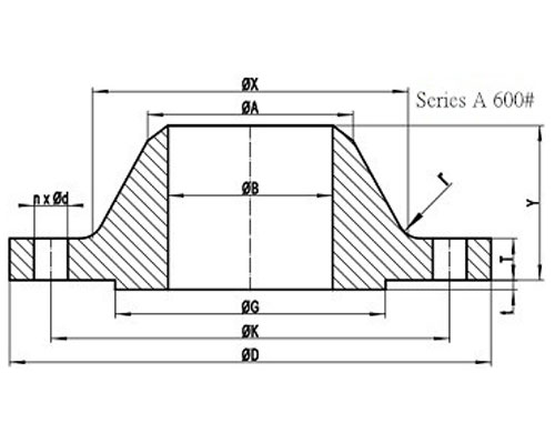
ASME B16.47 Series A 600# Welding Neck Flange with RF

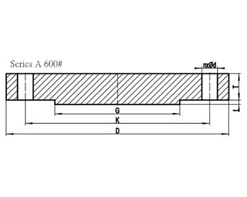
ASME B16.47 Series A Class 600 Blind Flange with RF
DOWNLOAD ASME B16.47 SERIES A FLANGES CLASS 600 DIMENSIONS AND TECHNICAL DRAWINGS PDF
Get Complete details of ANSI/ASME B16.47 Standard Flange
600# B16.47 Series A Flanges Dimensions
B16.47 Dimensions in MM
| NPS |
D |
K |
G |
X |
| 26″ |
1015 |
914.4 |
749 |
748 |
| 28″ |
1075 |
965.2 |
800 |
803 |
| 30″ |
1130 |
1022.4 |
857 |
862 |
| 32″ |
1195 |
1079.5 |
914 |
918 |
| 34″ |
1245 |
1130.3 |
965 |
973 |
| 36″ |
1315 |
1193.8 |
1022 |
1032 |
| 38″ |
1270 |
1162.0 |
1054 |
1022 |
| 40″ |
1320 |
1212.8 |
1111 |
1073 |
| 42″ |
1405 |
1282.7 |
1168 |
1127 |
| 44″ |
1455 |
1333.5 |
1226 |
1181 |
| 46″ |
1510 |
1390.6 |
1276 |
1235 |
| 48″ |
1595 |
1460.5 |
1334 |
1289 |
| 50″ |
1670 |
1524.0 |
1384 |
1343 |
| 52″ |
1720 |
1574.8 |
1435 |
1394 |
| 54″ |
1780 |
1632.0 |
1492 |
1448 |
| 56″ |
1855 |
1695.4 |
1543 |
1502 |
| 58″ |
1905 |
1746.2 |
1600 |
1553 |
| 60″ |
1995 |
1822.4 |
1657 |
1610 |
General Note:
- All dimensions are in MM.
- D: outside diameter of flange.
- K: diameter of bolt circle.
- G: diameter of raised face.
- X: diameter of hub of flange.
| NPS |
A |
TBL |
TWN |
Y |
| 26″ |
660.4 |
125.5 |
108.0 |
222 |
| 28″ |
711.2 |
131.8 |
111.2 |
235 |
| 30″ |
762.0 |
139.7 |
114.3 |
248 |
| 32″ |
812.8 |
147.7 |
117.5 |
260 |
| 34″ |
863.6 |
154.0 |
120.7 |
270 |
| 36″ |
914.4 |
162.0 |
123.9 |
283 |
| 38″ |
965.2 |
155.0 |
152.4 |
254 |
| 40″ |
1016.0 |
162.0 |
158.8 |
264 |
| 42″ |
1066.8 |
171.5 |
168.3 |
279 |
| 44″ |
1117.6 |
177.8 |
173.1 |
289 |
| 46″ |
1168.4 |
185.8 |
179.4 |
300 |
| 48″ |
1219.2 |
195.3 |
189.0 |
316 |
| 50″ |
1270.0 |
203.2 |
195.9 |
329 |
| 52″ |
1320.8 |
209.6 |
203.2 |
337 |
| 54″ |
1371.6 |
217.5 |
209.6 |
349 |
| 56″ |
1422.4 |
225.5 |
217.5 |
362 |
| 58″ |
1473.2 |
231.8 |
222.3 |
370 |
| 60″ |
1524.0 |
242.9 |
233.4 |
389 |
General Note:
- All dimensions are in MM.
- A: Diameter of hub top of WN.
- TBL: minimum thickness of blind flange.
- TWN: minimum thickness of WN flange.
- Y: length through hub of WN.
- t: 7mm height of RF for Class 600 Series A flange.
| NPS |
n |
d |
l |
r |
| 26″ |
28 |
2 |
1-7/8 |
13 |
| 28″ |
28 |
2-1/8 |
2 |
13 |
| 30″ |
28 |
2-1/8 |
2 |
13 |
| 32″ |
28 |
2-3/8 |
2-1/4 |
13 |
| 34″ |
28 |
2-3/8 |
2-1/4 |
14 |
| 36″ |
28 |
2-5/8 |
2-1/2 |
14 |
| 38″ |
28 |
2-3/8 |
2-1/4 |
14 |
| 40″ |
32 |
2-3/8 |
2-1/4 |
14 |
| 42″ |
28 |
2-5/8 |
2-1/2 |
14 |
| 44″ |
32 |
2-5/8 |
2-1/2 |
14 |
| 46″ |
32 |
2-5/8 |
2-1/2 |
14 |
| 48″ |
32 |
2-7/8 |
2-3/4 |
14 |
| 50″ |
28 |
3-1/8 |
3 |
14 |
| 52″ |
32 |
3-1/8 |
3 |
14 |
| 54″ |
32 |
3-1/8 |
3 |
14 |
| 56″ |
32 |
3-3/8 |
3-1/4 |
16 |
| 58″ |
32 |
3-3/8 |
3-1/4 |
16 |
| 60″ |
28 |
3-5/8 |
3-1/2 |
17 |
General Note:
- n: number of bolt holes.
- d: diameter of bolt hole.
- l: diameter of bolt.
- r: minimum fillet radius for WN.
- d and l are in inch units, while r is in mm unit.
ASME B16.47 Series A Class 600 Flanges Industries and Applications
Widely used in the industries
- Pumps, Valves, and vessels in manufacturing and food processing.
- Pipe connections in industrial waterworks.
- Heat exchangers and heating systems of all sizes.
- Mining support.
- Nuclear power systems.
- Plumbing and mechanical systems.
- Assemblies in the oil, gas, and petrochemical industries.
- Fire protection systems.
ASME B16.47 Series A Class 600 Flanges Supply and Export Network
List of Cities and Countries


