ASME B16.47 Series A Flanges Class 150 Dimensions and Technical Drawings

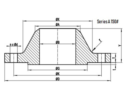
ASME B16.47 Series A 150# Welding Neck Flange with RF

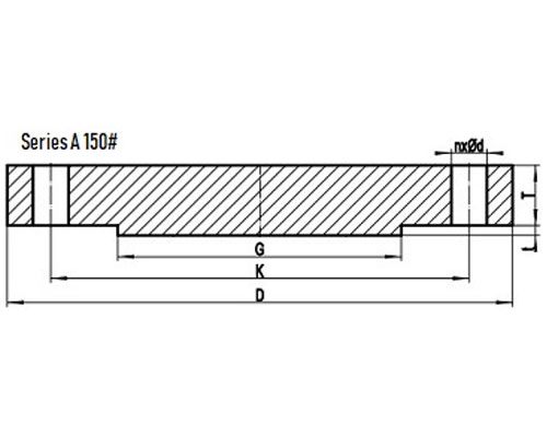
ASME B16.47 Series A Class 150 Blind Flange with RF
DOWNLOAD ASME B16.47 SERIES A FLANGES CLASS 150 DIMENSIONS AND TECHNICAL DRAWINGS PDF
Get Complete details of ANSI/ASME B16.47 Standard Flange
150# B16.47 Series A Flanges Dimensions
B16.47 Dimensions in MM
| NPS |
D |
K |
G |
X |
| 26″ |
870 |
806.4 |
749 |
676 |
| 28″ |
925 |
863.6 |
800 |
727 |
| 30″ |
985 |
914.4 |
857 |
781 |
| 32″ |
1060 |
977.9 |
914 |
832 |
| 34″ |
1110 |
1028.7 |
965 |
883 |
| 36″ |
1170 |
1085.8 |
1022 |
933 |
| 38″ |
1240 |
1149.4 |
1073 |
991 |
| 40″ |
1290 |
1200.2 |
1124 |
1041 |
| 42″ |
1345 |
1257.3 |
1194 |
1092 |
| 44″ |
1405 |
1314.4 |
1245 |
1143 |
| 46″ |
1455 |
1365.2 |
1295 |
1197 |
| 48″ |
1510 |
1422.4 |
1359 |
1248 |
| 50″ |
1570 |
1479.6 |
1410 |
1302 |
| 52″ |
1625 |
1536.7 |
1461 |
1353 |
| 54″ |
1685 |
1593.8 |
1511 |
1403 |
| 56″ |
1745 |
1651.0 |
1575 |
1457 |
| 58″ |
1805 |
1708.2 |
1626 |
1508 |
| 60″ |
1855 |
1759.0 |
1676 |
1559 |
General Note:
- All dimensions are in MM.
- D: outside diameter of flange.
- K: diameter of bolt circle.
- G: diameter of raised face.
- X: diameter of hub of flange.
| NPS |
A |
TBL |
TWN |
Y |
| 26″ |
660.4 |
66.7 |
66.7 |
119 |
| 28″ |
711.2 |
69.9 |
69.9 |
124 |
| 30″ |
762.0 |
73.1 |
73.1 |
135 |
| 32″ |
812.8 |
79.4 |
79.4 |
143 |
| 34″ |
863.6 |
81.0 |
81.0 |
148 |
| 36″ |
914.4 |
88.9 |
88.9 |
156 |
| 38″ |
965.2 |
85.8 |
85.8 |
156 |
| 40″ |
1016.0 |
88.9 |
88.9 |
162 |
| 42″ |
1066.8 |
95.3 |
95.3 |
170 |
| 44″ |
1117.6 |
100.1 |
100.1 |
176 |
| 46″ |
1168.4 |
101.6 |
101.6 |
184 |
| 48″ |
1219.2 |
106.4 |
106.4 |
191 |
| 50″ |
1270.0 |
109.6 |
109.6 |
202 |
| 52″ |
1320.8 |
114.3 |
114.3 |
208 |
| 54″ |
1371.6 |
119.1 |
119.1 |
214 |
| 56″ |
1422.4 |
122.3 |
122.3 |
227 |
| 58″ |
1473.2 |
127.0 |
127.0 |
233 |
| 60″ |
1524.0 |
130.2 |
130.2 |
238 |
General Note:
- All dimensions are in MM.
- A: Diameter of hub top of WN.
- TBL: minimum thickness of blind flange.
- TWN: minimum thickness of WN flange.
- Y: length through hub of WN.
- t: 2mm height of RF for Class 150 Series A flange.
| NPS |
n |
d |
l |
r |
| 26″ |
24 |
1-3/8 |
1-1/4 |
10 |
| 28″ |
28 |
1-3/8 |
1-1/4 |
11 |
| 30″ |
28 |
1-3/8 |
1-1/4 |
11 |
| 32″ |
28 |
1-5/8 |
1-1/2 |
11 |
| 34″ |
32 |
1-5/8 |
1-1/2 |
13 |
| 36″ |
32 |
1-5/8 |
1-1/2 |
13 |
| 38″ |
32 |
1-5/8 |
1-1/2 |
13 |
| 40″ |
36 |
1-5/8 |
1-1/2 |
13 |
| 42″ |
36 |
1-5/8 |
1-1/2 |
13 |
| 44″ |
40 |
1-5/8 |
1-1/2 |
13 |
| 46″ |
40 |
1-5/8 |
1-1/2 |
13 |
| 48″ |
44 |
1-5/8 |
1-1/2 |
13 |
| 50″ |
44 |
1-7/8 |
1-3/4 |
13 |
| 52″ |
44 |
1-7/8 |
1-3/4 |
13 |
| 54″ |
44 |
1-7/8 |
1-3/4 |
13 |
| 56″ |
48 |
1-7/8 |
1-3/4 |
13 |
| 58″ |
48 |
1-7/8 |
1-3/4 |
13 |
| 60″ |
52 |
1-7/8 |
1-3/4 |
13 |
General Note:
- n: number of bolt holes.
- d: diameter of bolt hole.
- l: diameter of bolt.
- r: minimum fillet radius for WN.
- d and l are in inch units, while r is in mm unit.
ASME B16.47 Series A Class 150 Flanges Industries and Applications
Widely used in the industries
- Pumps, Valves, and vessels in manufacturing and food processing.
- Pipe connections in industrial waterworks.
- Heat exchangers and heating systems of all sizes.
- Mining support.
- Nuclear power systems.
- Plumbing and mechanical systems.
- Assemblies in the oil, gas, and petrochemical industries.
- Fire protection systems.
ASME B16.47 Series A Class 150 Flanges Supply and Export Network
List of Cities and Countries


